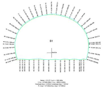
It shows graphically the differences between the surveyed cross-sections and the tunnel templates.
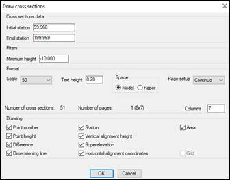
The following data is requested:
Initial station: Station from which measured points to be drawn are sought.
Final station: Station up to which measured points to be drawn are sought.
Minimum Height: Height with respect to the grade line for cutting the cross-sections and theoretical cross-section, by a horizontal line.
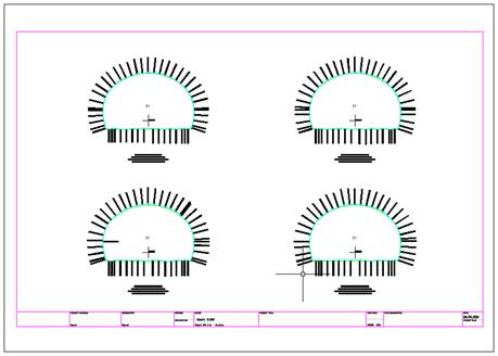
The elements one wishes to show can be selected in the Drawing section, as can the Scale, Text Height, Space (Model or Paper) and Drawing Format. The latter has options for drawing Cross-Sections in Continuous mode or on several sheets of DIN-A0, DIN-A1, DIN-A2, DIN-A3 o DIN-A4 paper. The option of also drawing one profile per sheet (DIN-A4) is also offered in the Individual option.
The drawing option in paper model allows one to use the CAD command Publish to print the cross-sections in PDF.
The elements making up the drawing include:
Point Number: Number of the points taken in the field.
Point Height: Height of the points taken in the field.
Difference: Perpendicular distance to the tunnel cross-section from the point measured.
Dimensioning Lines: Lines that join the point taken and its projection on the tunnel’s theoretical cross-section.
Station: Theoretical station calculated by regression.
Vertical Alignment Height: Vertical alignment height at the theoretical station.
Superelevation: Left-hand superelevation at the theoretical station.
Horizontal Alignment Coordinates: X and Y coordinates of the ground plan alignment at the theoretical station.
Area: Undercut and overcut areas and total areas of the theoretical and measured cross-sections at the theoretical station.
Grid: Is only activated when the Individual option is selected in Drawing Format. Shows a grid to mark distances and heights.
You are requested to select an insertion point for the drawing when OK is clicked. It should be taken into account that tunnel templates are only drawn when measured points have been found depending on the filters indicated. It could therefore happen that no drawing is generated.